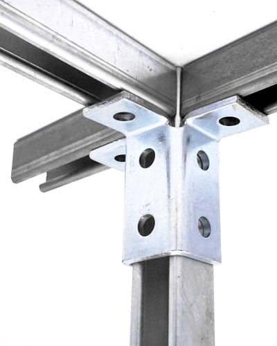

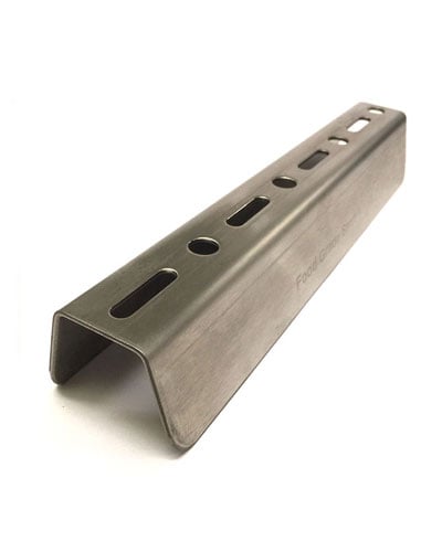
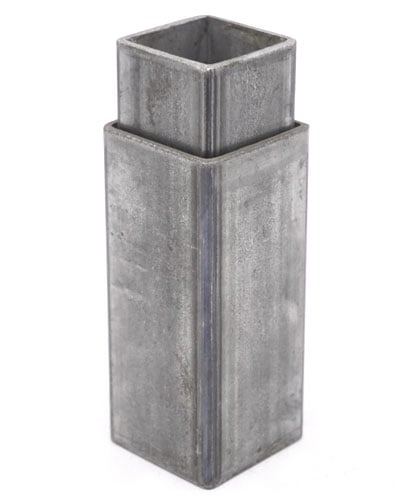


Unistrut P1001 1-5/8'' x 3-1/4'' Double Channel, 12 Gauge
Sku:
P1001
UOM: LGT

Sku:
P1001
UOM: LGT
Unistrut Buffalo is a division of Eberl Iron Works, Inc.
![]()
| Pricing SKU | P1001-10GR |
|---|---|
| SKU | P1001 |
| Pack Size | Length |
| UOM | LGT |
| Brand | Unistrut |
MATERIAL
Unistrut channels are accurately and carefully cold formed to size from low-carbon strip steel.
All spot-welded combination members, except P1001T, are welded 3" (76 mm) maximum on center.
STEEL: PLAIN
12 Ga. (2.7 mm), 14 Ga.(1.9 mm) and
16 Ga. (1.5 mm) ASTM A1011 SS GR 33
STEEL: PRE-GALVANIZED
12 Ga. (2.7 mm), 14 Ga. (1.9 mm) and
16 Ga. (1.5mm) ASTM A653 GR 33
For other materials, see Special Metals or Fiberglass sections.
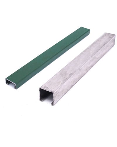
FINISHES
All channels are available in:
*** Perma Green finish is a commercial grade finish, and as such scuffs and scratch marks are to be expected. If a flawless finish is desired, it is recommended to apply a matching touch up paint ***
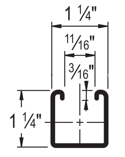
DIMENSIONS
Imperial dimensions are illustrated in inches. Metric dimensions are shown in millimeters and rounded to one decimal place.
STANDARD LENGTHS
Standard lengths are 10 feet (3.05m) and 20 feet (6.10m). Tolerances are ±1⁄8" (3 mm). Special lengths are available for a small cutting charge with a tolerance of ±1⁄8" (3 mm).
CURVED CHANNEL
Contact your local Unistrut Service Center or Unistrut Corporation for more information.
LOAD DATA
All beam and column load data pertains to carbon steel and stainless steel channels. Load tables and charts are constructed to be in accordance with the SPECIFICATION FOR THE DESIGN OF COLD-FORMED STEEL STRUCTURAL MEMBERS 2007 EDITION published by the AMERICAN IRON AND STEEL INSTITUTE USING ASD METHOD. Loads are based on 33 ksi steel cold formed to 42 ksi.
| Type of Load | Safety Factor to Yield Strength | Safety Factor to Ultimate Strength |
| Beam Loads | 1.67 | 2.0 |
| Column Loads | 1.80 | 2.2 |
P1000 - BEAM LOADING |
Uniform Loading at Deflection | ||||
| Span (In) | Max Allowable Uniform Load (Lbs) | Deflection at Uniform Load (In) | Span/180 (Lbs) | Span/240 (Lbs) | Span/360 (Lbs) |
| 24 | 3500* | 0.02 | 3500* | 3500* | 3500* |
| 36 | 3190 | 0.07 | 3190 | 3190 | 3190 |
| 48 | 2390 | 0.13 | 2390 | 2390 | 2390 |
| 60 | 1910 | 0.20 | 1910 | 1910 | 1620 |
| 72 | 1600 | 0.28 | 1600 | 1600 | 1130 |
| 84 | 1370 | 0.39 | 1370 | 1240 | 830 |
| 96 | 1200 | 0.51 | 1200 | 950 | 630 |
| 108 | 1060 | 0.64 | 1000 | 750 | 500 |
| 120 | 960 | 0.79 | 810 | 610 | 410 |
| 144 | 800 | 1.14 | 560 | 420 | 280 |
| 168 | 680 | 1.53 | 410 | 310 | 210 |
| 192 | 600 | 2.02 | 320 | 240 | 160 |
| 216 | 530 | 2.54 | 250 | 190 | 130 |
| 240 | 480 | 3.16 | 200 | 150 | 100 |
P1000 - COLUMN LOADING |
Maximum Column Load Applied at C.G. | ||||
| Unbraced Height (In) | Max Allowable Load at Slot Face (Lbs) | K = 0.65 (Lbs) |
K = 0.80 (Lbs) |
K = 1.0 (Lbs) |
K = 1.2 (Lbs) |
| 24 | 6430 | 24280 | 23610 | 22700 | 21820 |
| 36 | 6290 | 22810 | 21820 | 20650 | 19670 |
| 48 | 6160 | 21410 | 20300 | 18670 | 16160 |
| 60 | 6000 | 20210 | 18670 | 15520 | 12390 |
| 72 | 5620 | 18970 | 16160 | 12390 | 8950 |
| 84 | 5170 | 16950 | 13630 | 9470 | 6580 |
| 96 | 4690 | 14890 | 11190 | 7250 | 5040 |
| 108 | 4170 | 12850 | 8950 | 5730 | 3980 |
| 120 | 3690 | 10900 | 7250 | 4640 | ** |
| 144 | 2930 | 7630 | 5040 | ** | ** |
| Notes: * Load limited by spot weld shear. ** KL⁄r > 200 NR = Not Recommended. 1. Beam loads are given in total uniform load (W Lbs) not uniform load (w lbs/ft or w lbs/in). 2. Beam loads are based on a simple span and assumed to be adequately laterally braced. Unbraced spans can reduce beam load carrying capacity. Refer to Page 62 for reduction factors for unbraced lengths. 3. For pierced channel, multiply beam loads by the following factor: "KO" Series........95% "T" Series...........85% "HS" Series........90% "SL" Series.........85% "H3" Series.........90% "DS" Series........70% "WT" Series........85% 4. Deduct channel weight from the beam loads. 5. For concentrated midspan point loads, multiply beam loads by 50% and the corresponding deflection by 80%. For other load conditions refer to page 18. 6. All beam loads are for bending about Axis 1-1. |
|||||
| Parameter | P1000 | P1001 | |||
| Area of Section | 0.555 | In² | 1.111 | In² | |
| Axis 1-1 | |||||
| Moments of Inertia (I) | 0.185 | In⁴ | 0.928 | In⁴ | |
| Section Modulus (S) | 0.202 | In³ | 0.571 | In³ | |
| Rdius of Gyration (r) | 0.577 | In | 0.914 | In | |
| Axis 2-2 | |||||
| Moments of Inertia (I) | 0.236 | In⁴ | 0.471 | In⁴ | |
| Section Modulus (S) | 0.290 | In³ | 0.580 | In³ | |
| Rdius of Gyration (r) | 0.651 | In | 0.651 | In | |
Save paper! Download the most up to date version of Unistrut's General Engineering Catalog, right here, in digital format.
*Please note, catalog is in PDF format. You must have Adobe Reader (a FREE and trusted program) installed, to view. If you do not already have Adobe Reader installed, you may download it from Adobe's website. *Download times may vary, file is large.*